Communication Protocol - USB 🚧
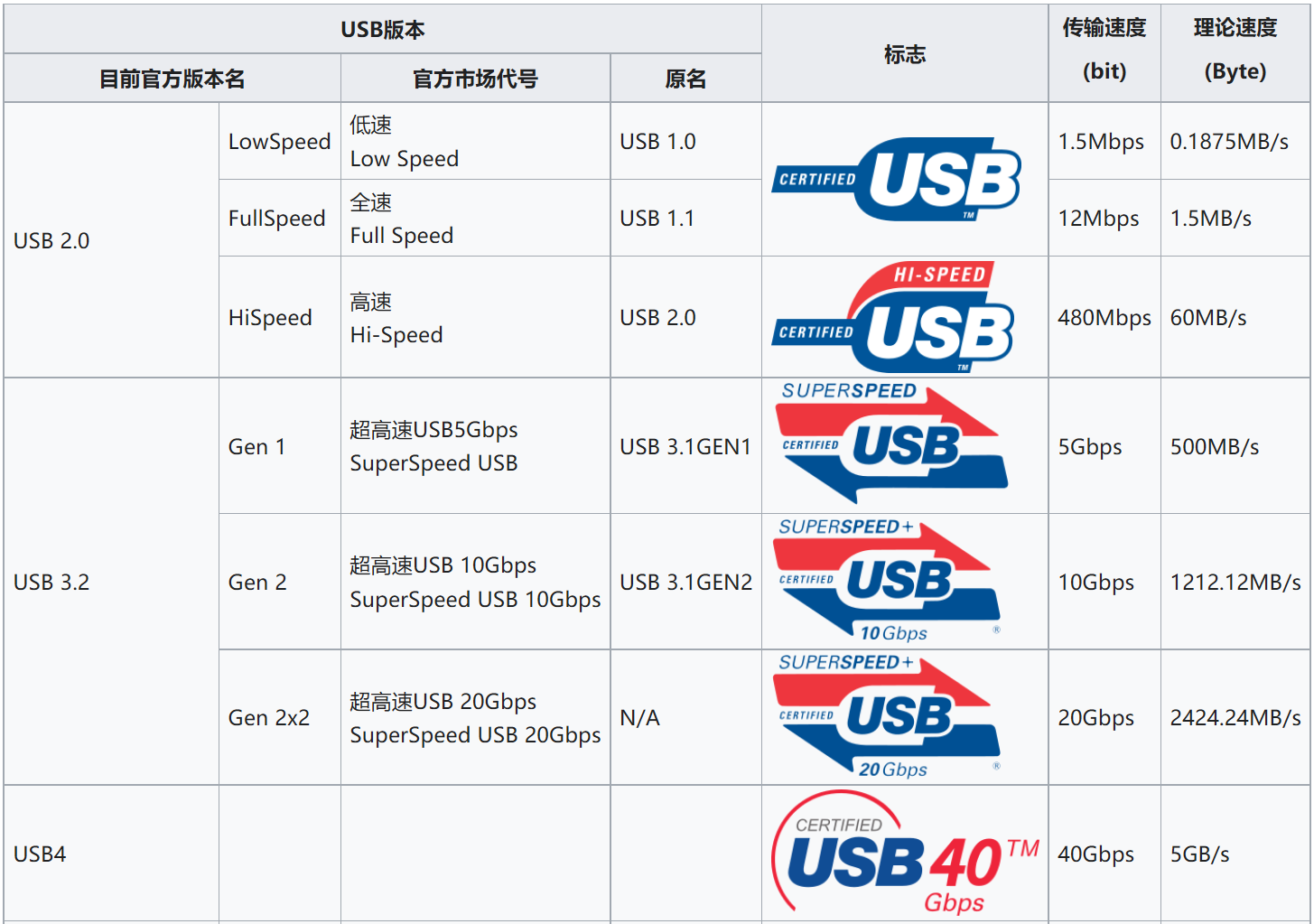
USB Versions
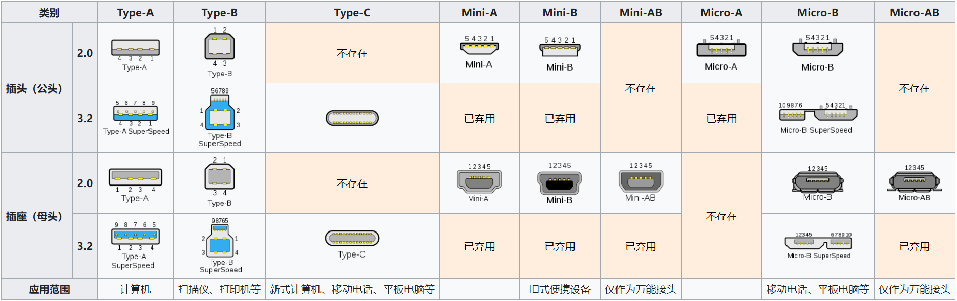
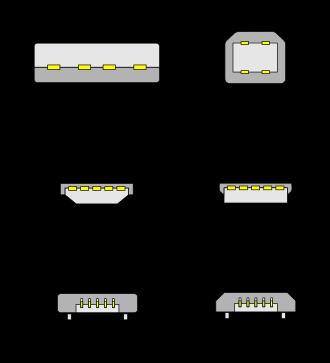
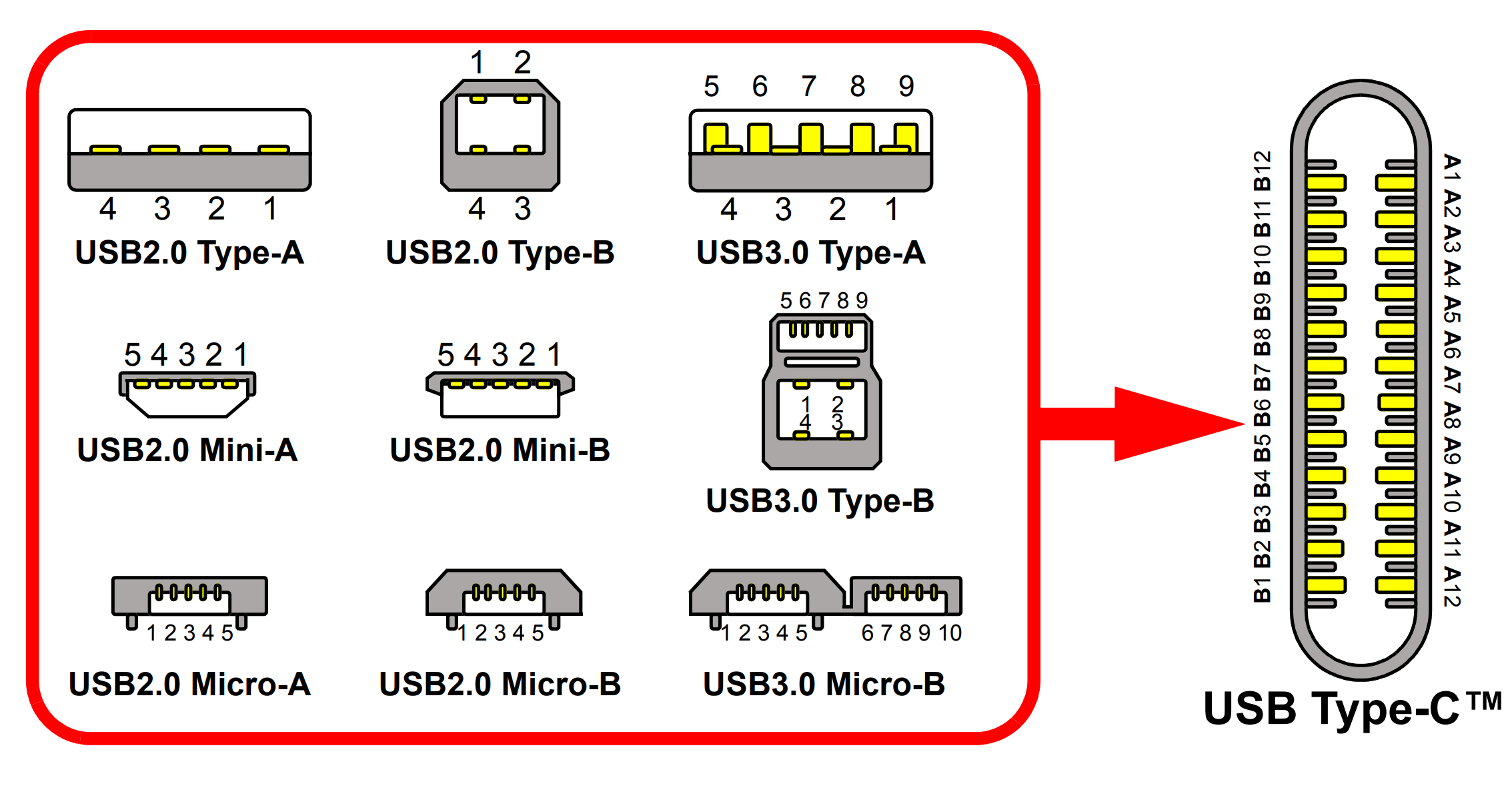
USB Mechanical Interface
Interface Definition - Standard USB:
| Pin | Function |
|---|---|
| 1 | VBUS (4.75-5.25 V) |
| 2 | D- |
| 3 | D+ |
| 4 | GND |
Interface Definition - Mini USB:
| Pin | Function | Color |
|---|---|---|
| 1 | VBUS (4.75-5.25 V) | Red |
| 2 | D- | White |
| 3 | D+ | Green |
| 4 | ID | |
| 5 | GND | Black |
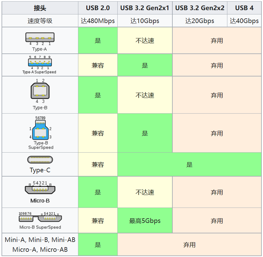
USB Plug and Version Compatibility
USB Type-C
Port Types
Data:
- Downstream Facing Port (DFP): Host/Downstream hub port. A typical example is the traditional standard Type-A port.
- Upstream Facing Port (UFP): Device/Upstream hub port. A typical example is the traditional standard Type-B port.
- Dual-Role Port (DRP): A port that switches between DFP and UFP ports before a connection event occurs. After the initial connection event, dynamic swapping can be negotiated through the USB Power Delivery protocol.
Power:
- Pull Current Source/Power Provider: Pull current of up to 5A at 5V-20V. A typical example is the traditional standard Type-A port.
- Sinking Current Source/Power Consumer: Sinking current of up to 5A at 5V-20V. A typical example is the traditional standard Type-B port.
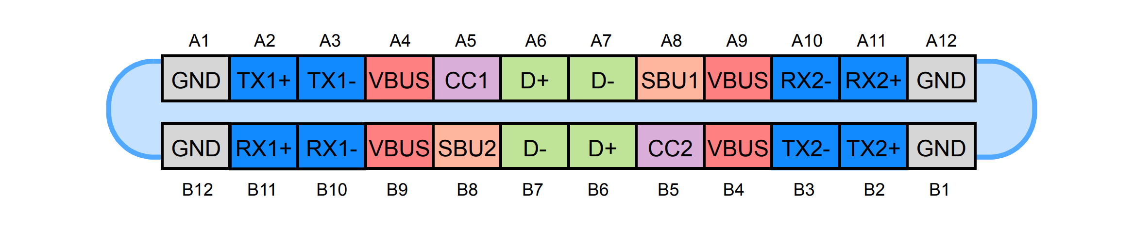
Pin Definitions
Type-C has male and female connectors, and most of their pins are mirrored.
Type-C Receptacle:
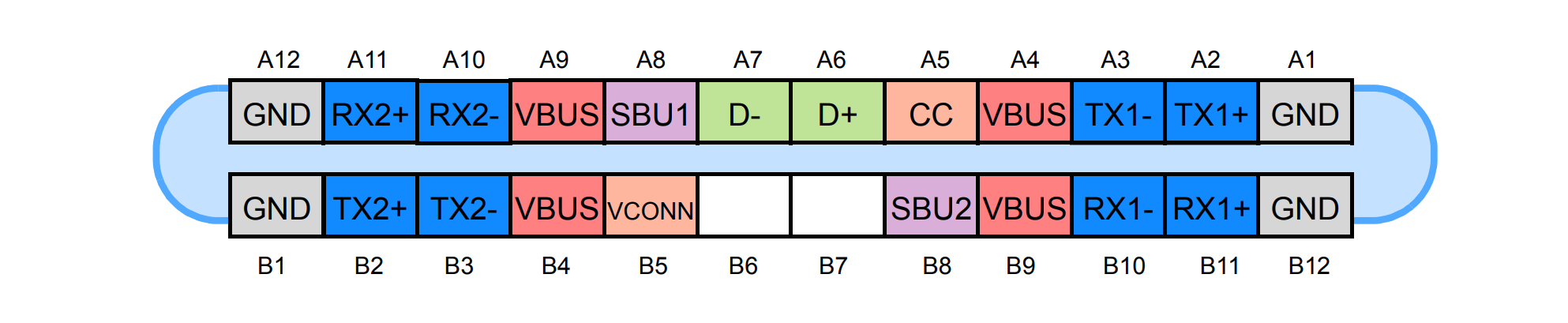
Type-C Plug:
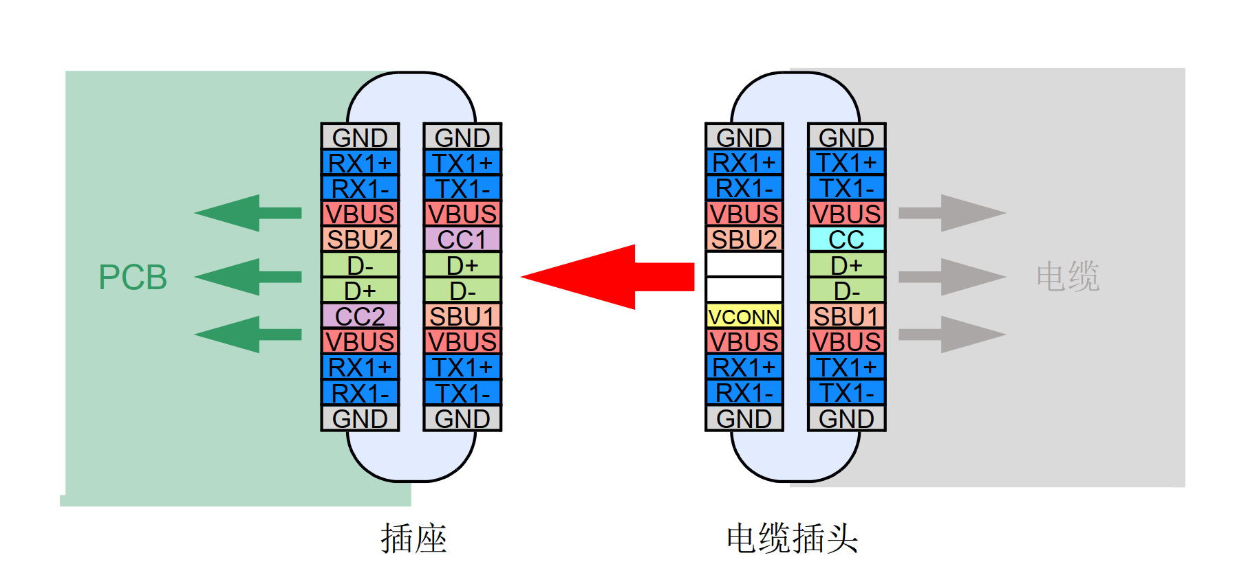
Docking Diagram (Full-Featured):
Pin Definitions:
| Pin | Name | Function | Detailed Description |
|---|---|---|---|
| A1 | GND | Power | Minimum support 60W (used with all VBUS) |
| A2 | TX1+ | USB3.1 or Alt | Differential pair with TX1- for 10 Gbps |
| A3 | TX1- | USB3.1 or Alt | Differential pair with TX1+ for 10 Gbps |
| A4 | VBUS | Power | Minimum support 60W (used with all VBUS) |
| A5 | CC1 | CC or VCONN | Used for orientation detection, current capability notification, and USB2.0 BMC communication |
| A6 | D+ | USB2.0 | — |
| A7 | D- | USB2.0 | — |
| A8 | SBU1 | Alt | Low-speed sideband signal, for Alt mode use only |
| A9 | VBUS | Power | Minimum support 60W (used with all VBUS) |
| A10 | RX2- | USB3.1 or Alt | Differential pair with RX2+ for 10 Gbps |
| A11 | RX2+ | USB3.1 or Alt | Differential pair with RX2- for 10 Gbps |
| A12 | GND | Power | Minimum support 60W (used with all VBUS) |
| B1 | GND | Power | Minimum support 60W (used with all VBUS) |
| B2 | TX2+ | USB3.1 or Alt | Differential pair with TX2- for 10 Gbps |
| B3 | TX2- | USB3.1 or Alt | Differential pair with TX2+ for 10 Gbps |
| B4 | VBUS | Power | Minimum support 60W (used with all VBUS) |
| B5 | CC2 | CC or VCONN | Used for orientation detection, current capability notification, and USB2.0 BMC communication |
| B6 | D+ | USB2.0 | — |
| B7 | D- | USB2.0 | — |
| B8 | SBU2 | Alt | Low-speed sideband signal, for Alt mode use only |
| B9 | VBUS | Power | Minimum support 60W |
| B10 | RX1- | USB3.1 or Alt | Differential pair with RX1+ for 10 Gbps |
| B11 | RX1+ | USB3.1 or Alt | Differential pair with RX1- for 10 Gbps |
| B12 | GND | Power | Minimum support 60W |
Power Supply Agreement:
| Mode | Nominal Voltage | Maximum Current |
|---|---|---|
| USB2.0 | 5V | 500 mA |
| USB3.0/USB3.1 | 5V | 900 mA |
| USB BC1.2 | 5V | 1.5A |
| USB Type-C Current @ 1.5A | 5V | 1.5A |
| USB Type-C Current @ 2.0A | 5V | 3.0A |
| USB PD | Up to 20V | Up to 5A |
CC Pins
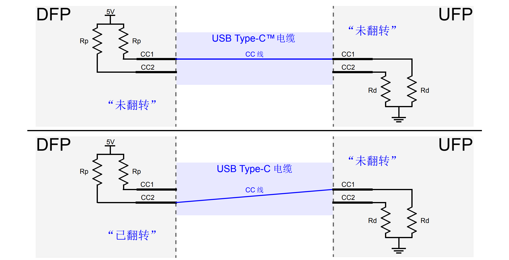
The pull-up and pull-down resistors used on the CC pins depend on whether it is a Downstream Facing Port (DFP), an Upstream Facing Port (UFP), or an Electronically Marked/Active Cable. The functionality of insertion/removal detection, orientation detection, and current capability notification must always be achieved through port monitoring.
Host / Downstream Facing Port (DFP) uses pull-up resistors. The pull-up resistor Rp must be connected to both CC1 and CC2 pins and pulled up to 3.3V/5V/current source. The value of the pull-up resistor determines the device's power supply current capability through the port, as shown in the table below:
| DFP Power Supply Current Capability | Pull-up to 4.75V~5.5V | Pull-up to 3.3V±5% | Pull-up to 1.7~5.5V current source |
|---|---|---|---|
| Default USB Power (USB2.0-500mA, USB3.0-900mA) | 56kΩ±20% | 36kΩ±20% | 80µA±20% |
| 1.5A@5V | 22kΩ±5% | 12kΩ±5% | 180µA±8% |
| 3A@5V | 10kΩ±5% | 4.7kΩ±5% | 330µA±8% |
Device / Upstream Facing Port (UFP) uses pull-down resistors or voltage clamp. The value of the pull-down resistor Rd is fixed at 5.1kΩ±10%.
For cable orientation detection, if CC1 pin detects a valid pull-up or pull-down, it represents the normal orientation (not flipped); if CC1 pin does not detect it, it represents the flipped orientation:
References and Acknowledgements
Original: https://wiki-power.com/
This post is protected by CC BY-NC-SA 4.0 agreement, should be reproduced with attribution.This post is translated using ChatGPT, please feedback if any omissions.